Regular readers will remember my whining about the poor precision of both infra-red and ultrasonic sensors. But today, the Raspberry Pi / Dyalog APL – controlled “DyaBot” was observed driving on a dinner table – where the slightest navigational error could mean a 3-foot plunge and certain death! How can this be?
The answer is: the “PiCam” finally arrived last week!!!
Capturing Images with The PiCam
I no longer need to complain about sonar beams being up to 30 degrees wide: the PiCam has a resolution of up to 1080×1920 pixels! So all we need is some software to interpret the bits…First, we capture images using the “raspistill” command:
raspistill -rot 90 -h 60 -w 80 -t 0 -e bmp -o ahead.bmp
The parameters rotate the image 90 degrees (the camera is mounted “sideways”), set the size to 60 x 80 pixels (don’t need more for navigation), take the picture immediately, and store the output in a file called “ahead.bmp”. (Documentation for the camera and related commands can be found on the Raspberry Pi web page.) Despite the small number of pixels, the command takes a full second to execute – anyone who knows a way to speed up the process of taking a picture, please let me know!
In the video, each move takes about 3 seconds, this is simply because each cycle is triggered by a browser refresh of the page after 3 seconds. Capturing the image takes about 1 second, the “image analysis” about 40 milliseconds, so we could be driving a lot faster with a bit of Javascript on the client side (watch this space).
Extracting BitMap Data
Under Windows, Dyalog APL has a built-in object for reading BitMap files, but at the moment, the Linux version does not have an equivalent. Fortunately, extracting the data using APL is not very hard (after you finish reading about BMP files on WikiPedia):
tn←'ahead.bmp' ⎕NTIE 0     ⍝ Open "native" file
(offset hdrsize width height)←⎕NREAD tn 323 4 10
                           ⍝ ↑↑↑ Read 4 Int32s from offset 10
data←⎕NREAD tn 80 (width×height×3) offset ⍝ Read chars (type 80)
data←⊖⎕UCS(height width 3)⍴data ⍝ Numeric matrix, reverse rows
The above gives us a 60 by 80 by 3 matrix containing (R,G,B) triplets. This code assumes that BMP file is in the 24-bit format created by raspistill; I will extend the code to handle all BMP formats (2, 16 and 256 colours) and post it when complete – but the above will do for now.
Where’s the Edge?
At Iverson College last week, I demonstrated the DyaBot driving on a table with a green tablecloth, using code which compared the ratio between R,G,B values to an average of a sample of green pixels from one shot. Alas, I prepared the demo in the morning and, when the audience arrived, there was much more (yellowish) light coming in through the window. This changed the apparent colour so much that the bot decided that the side of the table facing the window was now unsafe, and it cowered in the darkness.
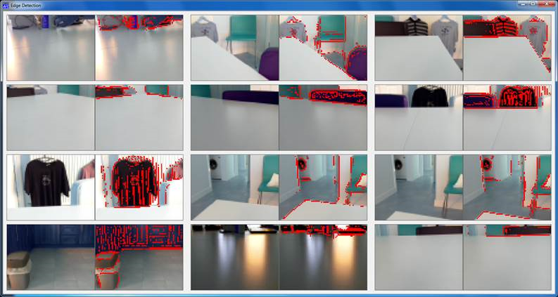
Fortunately, I was talking to a room full of very serious hackers, who sent me off to Wikipedia to learn about “kernels” as a tool for image processing. Armed with a suitable edge detection kernel, I was able to test this new algorithm on a dozen shots taken at different angles with the PiCam. Each pair of images below has the original on the left, and edges coloured red on the right. Notice that, although the colour of the table varies a lot when viewed from different directions – especially when there is background glare – the edges are always correctly identified:
Except for the image at the bottom left, where the bot is so close to the edge that the table is not visible at all (and the edge is the opposite wall of the room, ten feet away), we seem to have a reliable tool.
The PiServer Page
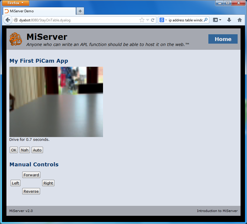
The code to drive the bot is embedded in a “PiServer” (MiServer running on a Rasperry Pi) web page. Each refresh of the page takes a new picture, extracts the bits, and calls the main decision-making function. The suggested action (turn or drive straight ahead) is displayed in the form, and the user has the choice of pressing OK to execute the command, pressing the “Nah” button to take a new photo and try again (after moving the bot, changing the lighting in the room, or editing the code). There are also four “manual” buttons for moving the Bot. After testing the decision-making abilities of the code, brave programmers press the “Auto” button, allowing the robot to drive itself without waiting for confirmation before each command (see the video at the start of this post)!
The Code
The central decision-making function and the kernel computation function are listed below. The full code will be uploaded to the MiServer repository on GitHub, once it is finally adjusted after I find a way to attach the PiCam properly, rather than sticking it to the front of the Bot with a band-aid!
∇ r←StayOnTable rgb;rows;cols;table;sectors;good;size;edges
 ⍝ Based on input from PiCam, drive at random, staying on table
 ⍝ Return vector containing degrees to turn and
 ⍝               #seconds to drive before next analysis

 (rows cols)←size←2↑⍴rgb
 ⍝ First detect edges in each colour separately
 edges←EdgeDetectAll∘AK¨⊂[1 2]rgb
 ⍝ Call it an edge if any r, g or b result is >75% of original
 edges←∨/(↑[0.5]edges)>0.75×1 1↓¯1 ¯1↓rgb
 ⍝ Look for lowest edge in each column
 table←+⌿∧⍀~⊖edges
 ⍝ Divide into 3 equally sized sectors (left, centre, right)
 sectors←((⍴table)⍴(⌈(⍴table)÷3)↑1)⊂table
 ⍝ Find the LOWEST edge in each sector
 good←⌊/¨sectors

 :If good∧.>15 ⍝ More than 15 pixel rows of table in all sectors
    r←0,0.1⌈(good[2]-15)÷25 ⍝ Carry straight on for a while
 :Else ⍝ Some sectors have less than 15 pixel rows
    :If 0≠1↑previous ⋄ r←previous
        ⍝ Once started turning, keep turning the same way
    :Else
        r←((1+>/good[1 3])⊃45 ¯45),0 ⍝ Turn in "best" direction
    :EndIf
 :EndIf
 previous←r ⍝ Remember last turn for next decision
∇
The function AK (Apply Kernel), and the kernel are defined as follows:
∇ r←kernel AK data;shape
   shape←⍴kernel
   r←(1-shape)↓⊃+/,kernel×(¯1+⍳1↑shape)∘.⊖(¯1+⍳1↓shape)∘.⌽⊂data
∇

 EdgeDetectAll ⍝ Our 3x3 kernel
¯1 ¯1 ¯1
¯1  8 ¯1
¯1 ¯1 ¯1
Note the similarity of AK to the APL Code for Conway’s Game of Life!


 Follow